AERONET Instrument Troubleshooting Interface - Solutions for ASYMMETRIC ALMUCANTARS/HYBRIDS Flag
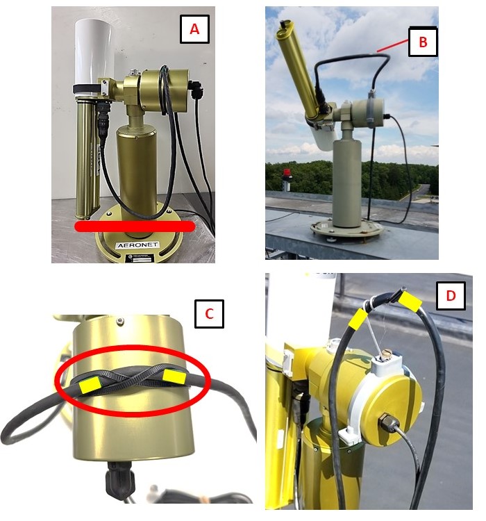
Description During an almucantar scan, the instrument sweeps through a wide range of azimuth angles at a fixed elevation. If the cable connecting the sensor head lacks sufficient slack, it can bind or pull on the robot as it rotates, restricting movement on one side of the scan. This physical restriction produces an asymmetric sky radiance pattern where one half of the scan does not mirror the other.
Condition(s) Check almucantar from -6 degrees to 0 and 0 to +6 degrees azimuth angle. Check hybrid from -6 degrees to 0 and 0 to +6 degrees scattering angle. Flag if increasing in both ranges, or decreasing in both ranges.
Cause: Typically, this is due to cable restriction during the almucantar scenario which requires a larger azimuthal range of motion than direct sun observations. Almucantars are disproportionately acquired in the early AM or late PM (large solar zenith angles), so this is the best time to observe the robot movements.
Check freedom of movement for the sensor head and cable length and orientation. Then observe an almucantar during automatic operation or manually activate one. If it's not possible to be on-site at these times, one can also do the following: Point the collimators (by hand) at the horizon line at the estimated sunset/sunrise position and make sure it can rotate in ~180 degrees in both directions from that point without binding. Note: Missing almucantars can also be indicated if the horizon view has been compromised by the placement of other instruments or growth of vegetation.
Model 5: SCN > run PARK, then GOSUN, then ALMUC Model T: SCENARIOS > run PARK, then GOSUN, then ALMUCANTAR
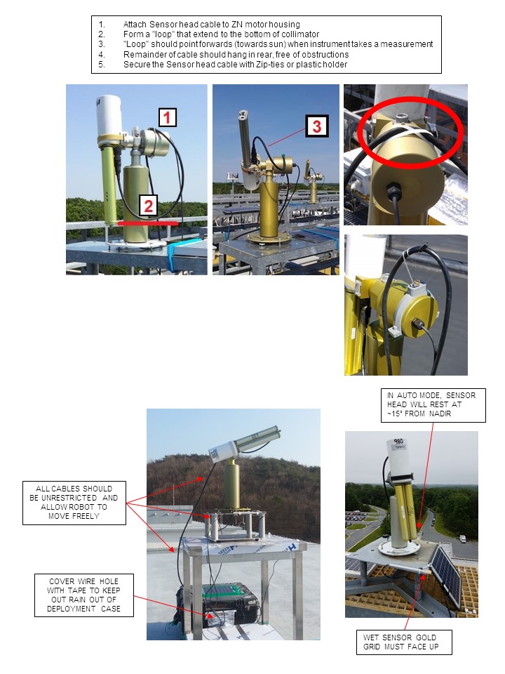
Solution Level 1 (< 5 minutes) 1. Watch the instrument run an almucantar (horizontal sky measurement) in Auto Mode or run it manually. Watch for the cables to catch or pull as the robot moves. 2. Adjust cables and ensure there is enough slack (See Check setup.jpg).
Solution Level 2 (more involved) 1. Look for abnormal movements or sounds when running PARK and GOSUN. After PARK the instrument should point towards nader and the robot claw should be level. After GOSUN the illuminated point should fall within ~1 cm of the pinhole marker at the base of the collimator. 2. Tie off cables close to the base of the robot so that they do not catch on anything below as the instrument rotates. 3. Redo the installation steps. (See installation guides for Model 5 and Model T)
Solution Level 3 (last resort) 1. Return the instrument to AERONET for maintenance.